Cat5 wiring, widely used in networking, needs skillful understanding for both IT pros and home networkers alike. Properly wiring and crimping Cat5/Cat5e lets you tailor make patch cables for modern networking. Before you set up your wired infrastructure, delve into Cat5 guidelines around twisted pairs, cabling norms, and termination tactics.
This article acts as a detailed, beginner-aimed guide for Cat5 wiring essentials.
Contents
What is a Cat5 Cable?
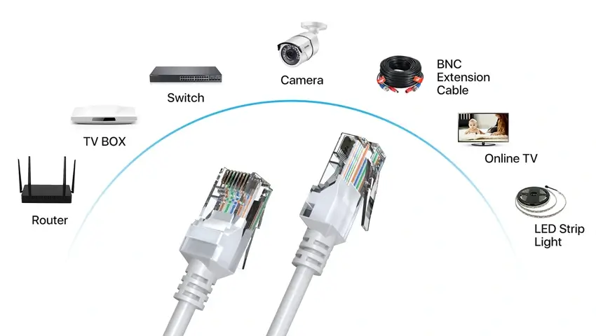
Cat5 cable, an Ethernet wiring used in computer networks, has four twisted pairs of copper wire and RJ45 connectors. It allows fast speeds up to 100 Mbps, common for LAN connections, and offers power over Ethernet (PoE) to devices like IP cameras and Wi-Fi access points.
Its key features include high-speed support and the ability to power devices over Ethernet, making it a versatile component in networking. Thus, Cat5 is essential for wired networks, offering high-speed data transmission, ideally for LAN and PoE connections.
How Cat5 Wiring Operates?
Inside a Cat5 cable, you can find four color-coded pairs of tightly twisted copper wire. Each pair follows a specific layout, a vital element for the cable to function appropriately.
Dive a bit deeper, and you’ll find two primary blueprints for Cat5 wiring – T568A and T568B. The exciting part? They dictate the order and the hue orientation of each wire within the RJ45 connectors at both ends of your Cat5 cable.
Now, here’s the important part: to enjoy superior signal quality that Cat5 cabling has to offer, strict adherence to the correct Cat5 wiring blueprint is a must. A little slip, like having diverse wiring standards at both ends, and you might find the connection dead. Such a mismatch could lead to network complications and interruptions.
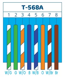
T-568A
The specifics of the T-568A standard: A well-structured color code sequence for Cat5 wiring.
T-568B
The specifics of the T-568B standard: A well-structured color code sequence for Cat5 wiring.
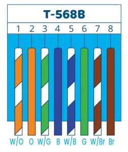
The only difference between the two standards is the orange and green wire pairs are swapped. It’s important to consult the correct Cat5 wiring diagram, depending on which standard you are using.
Cat5 Wiring Diagrams
There are two primary types of Cat5 wiring diagram schemes: straight-through and crossover, which determine how wire terminals are configured at each RJ45 connector on both ends of the cable.
- Straight-through Cat5 Wiring Diagram: Straight-through Cat5 wiring uses identical pinouts at both connectors, connecting wire pairs straight from one end to the other, enabling connectivity when a computer is directly linked to a network switch, router, or Ethernet wall port.
- Cross-over Cat5 Wiring Diagram: The crossover Cat5 wiring diagram swaps the transmit (Tx) wires on one connector with the receive (Rx) wires on another, reversing transmit and receive pairs between interfaces. This enables connectivity between like devices without a need for a central network device and is used to link two computers or switches directly.
In summary, the specific Cat5 wiring diagram is essential for configuring straight-through and crossover Cat5 cable connections.
Step-by-Step Guide to Wire a Cat5 Cable
Wiring your own Cat5 Ethernet cables is a straightforward process with the right tools. Here is a step-by-step guide to wiring a Cat5 cable:
- Gather essentials: Cat5(e)/Cat6 cable, RJ45 connectors, crimping, cutter/stripper.
- Ensure cable length is sufficient.
- Cut cable to desired length, strip about 1 inch of the sheath from each end, exposing four wire pairs.
- Untwist, align wire pairs according to T568A/B scheme, ensure uniform extension for RJ45 plug insertion.
- Insert wires into RJ45 connector, clip side down, ensuring they’re correctly ordered & inserted.
- Use crimping tool to secure the RJ45 connector, applying substantial force for solid contact.
- Repeat process on the other cable end, ensuring consistent wiring scheme usage.
- Test connection & crimp solidity before final network installation.
Components of Cat5 Wiring
There are a few basic components that make up a Cat5 wiring connection:
- Twisted Pair Cables or Cat5 have four twisted copper wire pairs, reducing noise interference for a robust connection.
- RJ45 Connectors, an 8-pin standard used on Cat5 and Ethernet, ensure easy and firm cable insertion.
- Ethernet Ports provide low power consumption and high reliability with LED indicators, ideal for optimal network performance.
Ethernet Cable Categories for PoE Cameras
When it comes to providing PoE power for security cameras, there are several categories of Ethernet cables that you can choose from. Each cable type offers distinct benefits and is suited for specific networking requirements. Here are the main categories of Ethernet cables for PoE cameras:
- Cat5e enhances Cat5 with better insulation and gigabit speeds, suitable for cost-effective PoE cameras.
- Cat6 offers higher performance and noise control, ideal for industrial cameras.
- Cat6a caters to speeds above 10Gbps, perfect for high-res cameras.
- Cat7 provides top-notch performance for stringent security needs, supporting speeds up to 100 Gbps.
Conclusion
By selecting the appropriate Ethernet cable category, you can provide necessary PoE power for security cameras in surveillance systems that offer efficient and reliable communication between systems. Higher-level cat5 ethernet wiring cables provide more noise protection and higher bandwidth, making them ideal for use in industrial and high-demand security application areas.
Related Posts
 Stop Being a Newbie — 5 Minutes to Learn About Network Basics
  Classroom Camera Laws: Navigating Privacy & Surveillance
  Wiring Security Camera Cables Made Easy: Tips and Techniques
  PoE Security System for Easier Installation: Don’t Worry about Wiring?
  Top 2 Wired Security Camera Systems 2023 (Reviews, Videos & Wiring Guide)