Contents
Understanding PoE Pinout: The Backbone of Modern Security Camera Systems
Introduction
In the world of modern surveillance technology, Power over Ethernet (PoE) has revolutionized how security cameras are installed and powered. Instead of running separate cables for power and data, PoE allows both to be transmitted through a single Ethernet cable. This not only simplifies installation but also makes systems cleaner, safer, and more efficient.
However, behind this convenient innovation lies an essential technical concept: the PoE pinout. The pinout determines how power and data are distributed within the Ethernet cable, and understanding it can make a huge difference in how well your security system performs. Whether you’re setting up IP cameras for home monitoring or designing a large commercial surveillance network, knowing how PoE pinout works ensures that your cameras receive stable power and smooth data transmission.
What Is Power over Ethernet (PoE)?
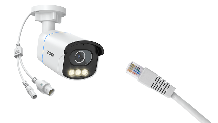
Power over Ethernet, often shortened as PoE, is a technology that enables a single Ethernet cable to deliver both electrical power and data to network devices. For security cameras, this means you don’t need to plug them into a separate power outlet. Instead, you can use the same Cat5e or Cat6 cable to transmit video signals and supply power directly from a PoE switch or PoE injector.
In traditional setups, you needed two cables — one for network connection and another for power. This not only made installations messy but also limited where cameras could be placed. PoE removes those limitations, allowing you to install cameras in high or outdoor locations without worrying about access to electrical outlets.
The result is a cleaner installation, reduced wiring costs, and easier maintenance. But to make all of this work, the internal wiring — the pinout — must follow a precise configuration.
The Basics of PoE Pinout
An Ethernet cable contains eight small wires, twisted into four pairs. These pairs are color-coded and connected to an RJ45 connector with eight pins. The pinout refers to the specific arrangement of these wires and determines which pins carry power and which carry data.
There are two main wiring standards for Ethernet cables — T568A and T568B. Both work with PoE, but the order of wire colors inside the connector differs slightly. Regardless of which standard you use, consistency is key: both ends of the same cable should follow the same wiring pattern to ensure stable data and power transmission.
In PoE systems, the device providing power is called the Power Sourcing Equipment (PSE) — typically a PoE switch or injector — and the device receiving power is called the Powered Device (PD), which in this case is your IP camera.
The PSE sends a low-level voltage signal to detect whether a connected device supports PoE. Once confirmed, it supplies the correct voltage and current through specific pairs of wires, according to the PoE standard in use.
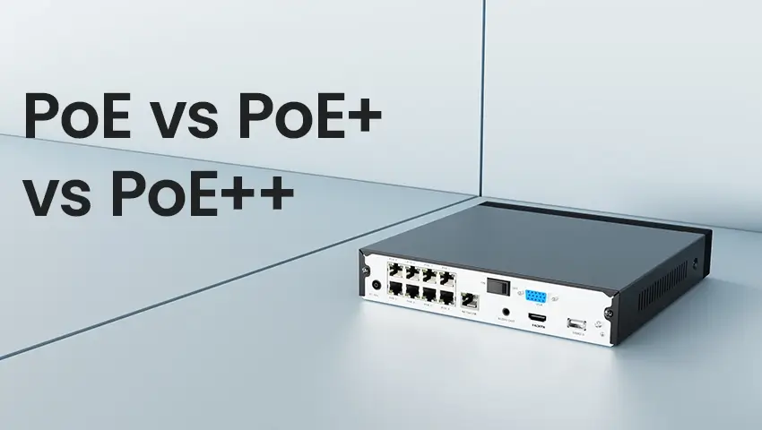
PoE Standards and Power Levels
Not all PoE setups deliver the same amount of power. Over time, different PoE standards have been developed to meet the growing energy demands of modern devices.
·IEEE 802.3af (PoE) provides up to 15.4 watts of power, suitable for basic fixed IP cameras.
·IEEE 802.3at (PoE+) delivers up to 30 watts, commonly used for PTZ (pan-tilt-zoom) cameras or cameras with built-in infrared.
·IEEE 802.3bt (PoE++ or 4PPoE) can provide up to 60–100 watts, ideal for advanced surveillance equipment with heaters, microphones, or powerful LEDs.
Understanding the power requirement of your camera ensures you choose the right PoE switch or injector, avoiding issues like unstable video feeds or cameras shutting down unexpectedly.
PoE Pinout Modes: Mode A and Mode B
PoE can transmit power through Ethernet cables in two primary ways — Mode A and Mode B. The main difference lies in which wire pairs are used to deliver the electrical current.
Mode A, often referred to as endspan, sends power and data through the same wire pairs. It typically uses pins 1, 2, 3, and 6. This mode is commonly used in PoE network switches because it allows power to be transmitted without needing additional hardware.
Mode B, also known as midspan, sends power through the unused wire pairs — pins 4, 5, 7, and 8 — in 10/100 Mbps networks. This mode is often used in PoE injectors, which are placed between a regular network switch and the powered device to add PoE capability.
For Gigabit Ethernet (1000 Mbps), all four wire pairs carry data, but power can still be transmitted over any of them without interference. Modern devices automatically detect which mode is being used and adjust accordingly.
Why PoE Pinout Matters for Security Cameras
At first glance, the pinout might seem like a minor technical detail, but in reality, it plays a critical role in the reliability of your surveillance system.
1. Ensures Stable Power Supply
If the power lines are connected incorrectly, the camera may fail to turn on or may operate intermittently. A correct pinout guarantees that each camera receives the right voltage consistently.
2. Improves Installation Efficiency
Knowing how PoE pinout works helps you select the right type of cable, connector, and switch. It also simplifies troubleshooting when something goes wrong, allowing you to pinpoint whether the issue lies in the power source, the cable, or the camera.
3. Protects Equipment from Damage
Incorrectly wired cables or mismatched PoE standards can send too much power to a device, potentially damaging the camera or the PoE switch. Understanding which pins carry current prevents such costly mistakes.
4. Enables Flexible Network Design
When designing a multi-camera system, proper knowledge of pinouts and PoE modes lets you plan cable routes and select switches more effectively, ensuring optimal performance across all devices.
Practical Tips for Setting Up PoE Cameras
If you’re installing PoE cameras yourself or managing a small surveillance network, a few best practices can help you achieve a stable and professional setup:
·Use High-Quality Cables: Always choose Cat5e or Cat6 cables from reputable brands. Inferior cables can cause data loss or voltage drops, especially over long distances.
·Avoid Excessive Cable Lengths: The standard maximum cable length for PoE is 100 meters (328 feet). If you need to go further, use a PoE extender or a powered switch in between.
·Check Power Compatibility: Before connecting, confirm your camera’s power requirements and ensure the PoE switch or injector supports the same standard (af, at, or bt).
·Label Everything: When installing multiple cameras, label both ends of each cable to avoid confusion later.
·Test Before Mounting: Connect and test each camera on the ground before mounting it on walls or ceilings. This helps identify any pinout or wiring issues early.
Common PoE Issues and How to Troubleshoot
Even with correct wiring, you may occasionally face problems such as a camera not powering up, weak video signals, or network drops. Most of these issues can be traced back to either cable quality, power limitations, or incorrect pin connections.
If a camera doesn’t power on, use a PoE tester or multimeter to confirm that voltage is present on the correct pins. If the video feed is unstable, the issue may be due to an underpowered PoE source — upgrading to a PoE+ switch or using a shorter cable often solves the problem. Replacing old or damaged cables with properly shielded Cat6 cables can also eliminate data interference.
Conclusion
The PoE pinout might not be the first thing you think about when setting up a security camera system, but it’s one of the most important factors behind reliable operation. By understanding how power and data are transmitted through Ethernet cables, you can install and maintain your cameras more efficiently and confidently.
From simple home setups to large commercial surveillance networks, PoE technology has made installations cleaner, safer, and more flexible. But it’s the precise pinout configuration that keeps everything running smoothly. So next time you connect a PoE camera, remember — those tiny pins inside the RJ45 connector are doing a lot more than you think. They’re carrying both the eyes and the energy of your entire security system.